Communication Range of Zigbee Product
This topic describes how to test the actual communication range between the Zigbee product and the gateway.
Test preparation
| Device | Description |
|---|---|
| Zigbee product | Zigbee product under test (Referred to as product hereinafter). |
| Zigbee gateway | Connect the product and the router. |
| UPS power bank | DC 12V output. Powers the router. |
| Portable power bank | USB 5V output. Powers the product. |
| 4G LTE router | UPS DC 12V power supply is required for the Zigbee gateway network connection. |
| Laptop computer | A packet capture software is required. |
| Mobile phone | Tuya app is required to check the reporting status and send commands to the device. |
Test principle
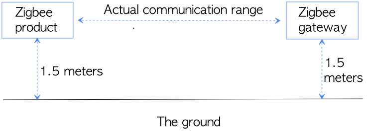
In an open outdoor area, connect the product to the gateway and increase the range between them. Assess the maximum communication range by the success rate of data reporting.
Test condition
Test environment
Open outdoor environment with light human and vehicle traffic. The test environment building is as follows.
Factors like weather, temperature and humidity, and day-and-night might cause variation of the medium between the product and the gateway, which might affect the test result.
Placement of product
-
Placement of gateway
Place the wireless gateway as close as possible to the router. Place the wired gateway to ensure that the network cable can connect to the router. Keep all the gateway antennas standing upward when testing. As it is shown below.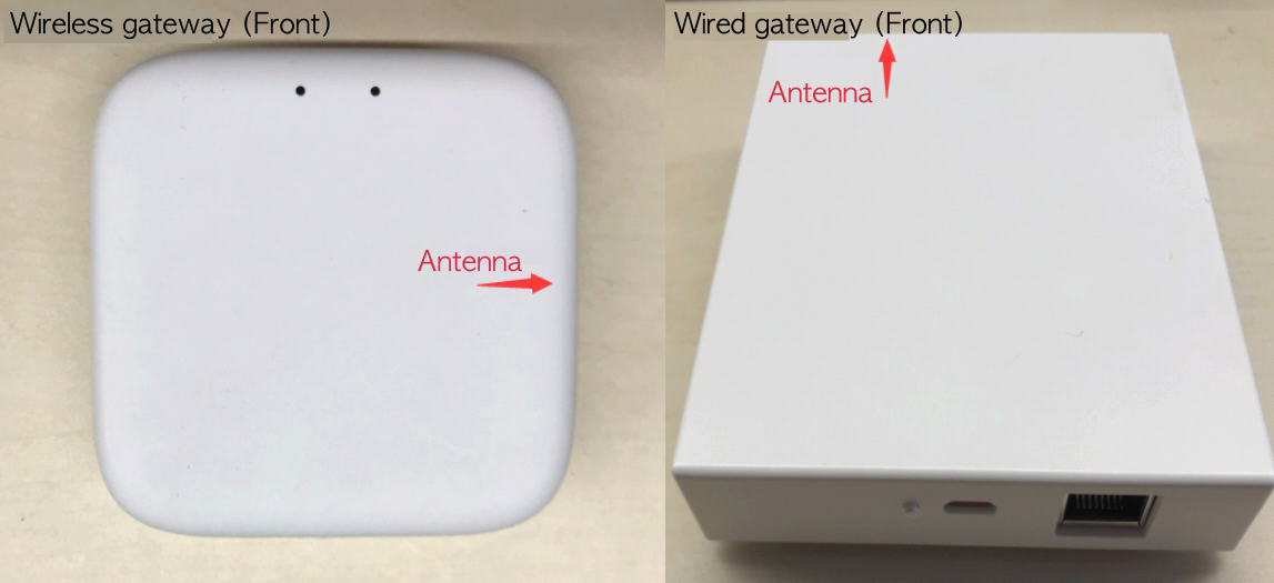
-
Position of product
It is required to test the maximum communication ranges with the front, sides, and rear of the antenna facing each product respectively. The following figure describes the contact sensor as an example.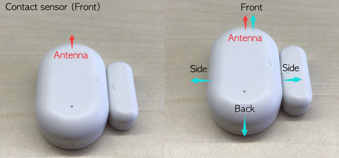
Maximum communication range
-
Add the Zigbee gateway with the SmartLife app and pair the product through the gateway.
-
Connect the gateway to the router and keep a ground clearance of 1.5 meters with a chair.
- The wired gateway can be connected directly to the router through the network cable.
- The wireless gateway shall be paired with the router’s Wi-Fi network.
-
After the product is powered on, place the product as required, and keep a ground clearance of about 1.5 meters.
-
Increase the range between the product and the gateway slowly and check the data variation.
- Check the device control status in the control panel on the SmartLife app.
- Check the packet capture data variation on the laptop.
The communication between the product and the gateway will be affected while moving. You need to keep continuous observation of the app’s control over the product.
-
Determine the maximum communication range.
When the app freezes or loses control over the product and the packet capture data loses, you stay still and observe.- If the app control and packet capture data resume in five minutes, keep increasing the range.
- If the app loses control over the product and the packet capture data loses for over 5 minutes, consider the range as the maximum communication range.
-
Change the placement of the product, with the front, sides, and rear of the antenna facing the gateway respectively. Then repeat the step 3 to 5 to test the maximum communication range.
Comparison and record
Comparison test
- In order to verify the communication capability of a product, multiple similar products are usually used for a comparison test. Take a standard sample as the reference for each test. For example, use a contact sensor as the standard product for comparison.
- In order to assess the data communication success rate of the product, the data communication success rate is usually tested from a fixed range. Within the range where the app holds stable control over the product and reports data properly, repeat the test 20 times and record the successes and failures for assessing success rate (successes/attempts).
Data record
The external environment data needs to be recorded in the test report: weather, temperature, and day-and-night. Record the data in a table like this:
-
The test table for the maximum communication range
Serial number Test item Test device Version Maximum range Remarks 1 2 3 4 5 6 -
The test table for data communication success rate of the product at a fixed range.
Serial number Test item Test device Version Number of tests Range 1 Range 2 Range 3 Remarks 1 2 3 4 5 6
Is this page helpful?
YesFeedbackIs this page helpful?
YesFeedback


