TYLC4 Module
This topic describes relevant information about TYLC4 module during MCU connection development.
Background information
- TYLC4 is a low power embedded Wi-Fi module developed by Tuya Smart. The module consists of a highly integrated radio-frequency identification (RFID) chip ESP8266 and a few peripheral components, with built-in Wi-Fi network protocol stack and various library functions.
- TYLC4 also has a low power 32-bit CPU, 1 MB flash, 50 KB static random access memory (SRAM), and rich peripheral resources.
- As a real time operating system (RTOS) platform, TYLC4 integrates all function libraries of Wi-Fi MAC and TCP/IP protocols. On this basis, you can develop your own embedded Wi-Fi products. For example, build prototypes of sockets, power strips, and switches.
For more information, see Wi-Fi module introduction — TYLC4.
Typical application diagram
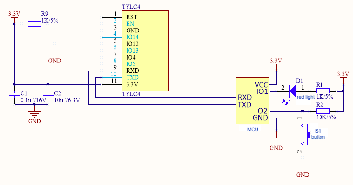
Figure 1 and Figure 2 are typical application diagrams of self-processing mode of TYLC4 module and MCU connection. Figure 3 and Figure 4 are typical application diagrams of coordinated processing mode of TYLC4 module and MCU connection.
S1 is a reset button of the Wi-Fi module, and LED1 is a status indicator light of the Wi-Fi module. The following table shows the relation between LED1 status and Wi-Fi module working status.
| LED1 status | LED1 display | Working status of Wi-Fi module |
|---|---|---|
| Flicker fast | On and off interval is 250 ms | Fast connection mode (Smartconfig mode) |
| Flicker slowly | On and off interval is 1,500 ms | Compatible mode (AP network configuration mode) |
| Always on | Always on | Wi-Fi module is connected to the router |
| Always off | Always off | Wi-Fi module is disconnected from the router |
Figure 1 is a reference diagram of self-processing mode of the module and 5V MCU communication.
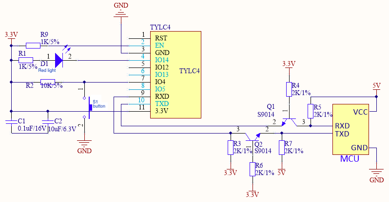
Figure 2 is a reference diagram of self-processing mode of the module and 3.3V MCU communication.
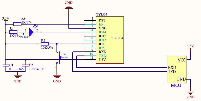
Figure 3 is a reference diagram of coordinated processing mode of the module and 5V MCU.
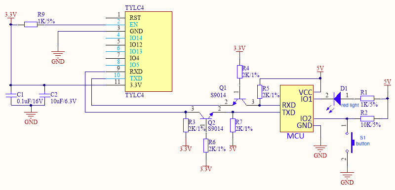
Figure 4 is a reference diagram of coordinated processing mode of the module and 3.3V MCU.
Design specification
-
Module power supply:
-
Power consumption during normal work: 3.3V/100mA. For a 3.3V module, recommended supply current is ≥ 300mA. Total capacitance value of external filter capacitor is greater than 10uF. When the 3.3V module is sending or receiving RF, the current increases by 50%.
-
In the PCB layout, power filter capacitors C1 and C2 at the power input pin shall be arranged near the VCC pin.
-
If MCU supply voltage is 3.3V, you can omit the signal level transfer circuit in the reference diagrams 1 and 2.
-
-
Module pin:
-
Serial ports TXD and RXD are connected to your MCU. Default settings are as follows. Baud: 9600, data bit: 8 bits, stop bit: 1 bit, no check bit, and no flow control. During power-on of the module, TXD pin prints some start information of the module. You can neglect the printing information of the serial port during this period. If you need to use this serial port as a general I/O port, contact R&D personnel of this company.
-
RST pin can reset the module hardware. It is valid in case of low electrical level. To use the RST pin, connect it to I/O port of MCU. Make sure that the electrical level is matched.
-
If required, the module can be connected to a button and a Wi-Fi status indicator light.
- S1 button in Figure 1 and Figure 2 is used to clear network configuration information of the module. Its function can be reused with normal functions of a smart product.
- LED1 indicator light in Figure 1 and Figure 2 is used to indicate the current Wi-Fi working status of the Wi-Fi module or smart product.
See Figure 1 if you use self-processing mode of the module. See Figure 2 if you use coordinated processing mode of the module.
-
Pins not in use can float.
-
-
Radio frequency (RF) of the module:
- IPEX port is reserved in the PCB, and can be connected to an antenna with an IPEX terminal.
- When an antenna with an IPEX terminal is used in the Wi-Fi module, it is recommended that the distance between the module antenna and other metal parts should be at least 10 mm, in order to optimize the Wi-Fi performance.
Is this page helpful?
YesFeedbackIs this page helpful?
YesFeedback


