HEWRQU1 Module Datasheet
Developed by Tuya, HEWRQU1 is a Wi-Fi module that is suitable for serial communication in which the level is changed from 5V TTL to 3.3V TTL. It consists of a highly integrated wireless RF chip (RTL 8710BN), an extension chip, and a DC-DC chip. Besides, it has a Wi-Fi network protocol stack and rich library functions inside. It further contains a low-power ARM CM4FCPU, a 2-MB flash memory, and a 256-KB SRAM.
Product overview
HEWRQU1 is an RTOS platform that integrates all function libraries of the Wi-Fi MAC and TCP/IP. On the basis of serial communication, you can develop embedded Wi-Fi products as required.
Features
- Low-power CPU, which can also function as an application processor
- The maximum clock rate: 125 MHz
- Operating voltage: 4.5 to 5.5V
- Peripheral: 1 UART
- Wi-Fi connectivity
- 802.11 b/g/ n_HT20 HT40
- Channels 1 to 14@2.4 GHz
- Support WPA, WPA2, WEP, and TKIP security modes
- Up to +18 dBm output power in 802.11b mode
- Support STA, AP, and STA+AP working modes
- Support SmartConfig and AP network configuration manners for Android and iOS devices
- Onboard PCB antenna
- Operating temperature: -20℃ to 85℃
Applications
- Intelligent buildings
- Smart household and home appliances
- Smart socket and light
- Industrial wireless control
- Baby monitor
- Network camera
- Intelligent bus
Module interfaces
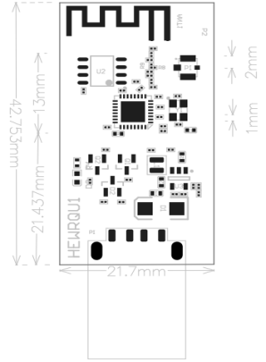
Dimensions and footprint
The dimensions of HEWRQU1 are 42.75±0.35 mm (L)×21.7±0.35 mm (W) ×4.5±0.15 mm (H).
The dimensions of HEWRQU1 are shown below:
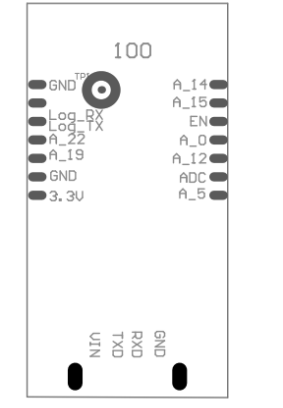
Pin definition
| Pin number | Symbol | Type | Function |
|---|---|---|---|
| 1 | A_14 | I/O | GPIO_14 |
| 2 | A_15 | I/O | GPIO_15 |
| 3 | EN | P | Enabling pin (low active) |
| 4 | A_0 | I/O | GPIO_0. It cannot be pulled up during powering on. |
| 5 | A_12 | I/O | GPIO_12 |
| 6 | ADC | AI | ADC port, the max input voltage 5V |
| 7 | A_5 | I/O | GPIO_5 |
| 8 | 3.3V | P | Power supply pin (3.3V) |
| 9 | GND | P | Power supply reference ground |
| 10 | A_19 | I/O | GPIO_19 |
| 11 | A_22 | I/O | GPIO_22 |
| 12 | Log_TX | I/O | UART_Log_TXD (used to display the internal information of the module) |
| 13 | Log_RX | I/O | UART_Log_RXD (used to display the internal information of the module) |
| 14 | GND | P | Power supply reference ground |
| 15 | VIN | I/O | External input voltage (5V) |
| 16 | TXD | I/O | UART0_TXD (user-side serial port) |
| 17 | RXD | I/O | UART0_RXD (user-side serial port) |
| 18 | GND | P | Power supply reference ground |
- P indicates power supply pins, I/O indicates input/output pins and AI indicates analog input pins.
- RST is only a reset pin and cannot be used for clearing network configuration information.
Definitions on test pins
| Pin Number | Symbol | I/O Type | Function |
|---|---|---|---|
| - |  |
I | Used for production tests of the module |
Test pins are not recommended.
Electrical parameters
Absolute electrical parameters
| Parameter | Description | Minimum value | Maximum value | Unit |
|---|---|---|---|---|
| Ts | Storage temperature | -40 | 125 | ℃ |
| VBAT | Power supply voltage | - | 5.5 | V |
| ESD voltage (human body model) | TAMB-25℃ | - | 2 | KV |
| ESD voltage (machine model) | TAMB-25℃ | - | 0.5 | KV |
Normal working conditions
| Parameter | Description | Minimum value | Typical value | Maximum value | Unit |
|---|---|---|---|---|---|
| Ta | Operating temperature | -20 | - | 85 | ℃ |
| VBAT | Power supply voltage | 4.5 | 5 | 5.5 | V |
| VIL | Low voltage input | -0.3 | - | VCC*0.25 | V |
| VIH | High voltage input | VCC*0.75 | - | VCC | V |
| VOL | Low voltage output | - | - | VCC*0.1 | V |
| VOH | High voltage output | VCC*0.8 | - | VCC | V |
| Imax | IO drive current | - | - | 16 | mA |
TX and RX power consumption
| Working Status | Mode | Rate | Transmit Power/Receive | Typical Value | Unit |
|---|---|---|---|---|---|
| Transmit | 11 b | 11Mbps | +17dBm | 285 | mA |
| Transmit | 11g | 54Mbps | +14.5dBm | 255 | mA |
| Transmit | 11n-HT20 | MCS7 | +13.5dBm | 235 | mA |
| Transmit | 11n-HT40 | MCS7 | +13.5dBm | 235 | mA |
| Receive | 11b | 11Mbps | Constantly receive | 90 | mA |
| Receive | 11g | 54Mbps | Constantly receive | 90 | mA |
| Receive | 11n-HT20 | MCS7 | Constantly receive | 90 | mA |
| Receive | 11n-HT40 | MCS7 | Constantly receive | 90 | mA |
Operating current
| Operating mode | Operating status, Ta = 25°C | Average value | Maximum value (Typical value) | Unit |
|---|---|---|---|---|
| Quick pairing | The module is in fast pairing state | 88 | 150 | mA |
| Hotspot | The module is in pairing state through the hotspot and the Wi-Fi indicator always flashes slowly | 95 | 245 | mA |
| Connected | The module is connected to the network and the Wi-Fi indicator is always on | 55 | 220 | mA |
The above parameters may vary with firmware functions.
RF parameters
Basic RF features
| Parameter | Description |
|---|---|
| Operating frequency | 2.412 to 2.484 GHz |
| Wi-Fi standard | IEEE 802.11 b/g/n (channels 1 to 14) |
| Data transmission rate | 11b: 1, 2, 5.5, and 11 (Mbps) 11g: 6, 9, 12, 18, 24, 36, 48, and 54 (Mbps) 11n: HT20 MCS 0 to 7; HT40 MCS 0 to 7 |
| Antenna type | PCB antenna |
TX performance
TX performance
| Parameter | Minimum value | Typical value | Maximum value | Unit |
|---|---|---|---|---|
| Average RF output power, 802.11b CCK Mode 11M | - | 17 | - | dBm |
| Average RF output power, 802.11g OFDM Mode 54M | - | 14.5 | - | dBm |
| Average RF output power, 802.11n HT20 Mode MCS7 | - | 13.5 | - | dBm |
| Average RF output power, 802.11n HT40 Mode MCS7 | - | 13.5 | - | dBm |
| Frequency error | -20 | - | 20 | ppm |
RX performance
RX sensitivity
| Parameter | Minimum value | Typical value | Maximum value | Unit |
|---|---|---|---|---|
| PER<8%, RX sensitivity, 802.11b DSSS Mode 11M | - | -90 | - | dBm |
| PER<10%, RX sensitivity, 802.11a OFDM Mode 54M | - | -73 | - | dBm |
| PER<10%, RX sensitivity, 802.11n OFDM Mode HT20-MCS7 | - | -70 | - | dBm |
Antenna
Antenna type
HEWRQU1 supports two types of antennas: Onboard PCB antenna and external antenna. By default, the onboard PCB antenna is preferred.
Interference reduction
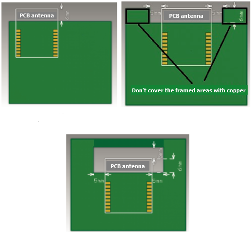
To ensure optimal Wi-Fi performance when the Wi-Fi module uses a PCB antenna, it is recommended that the antenna be at least 15 mm away from other metal parts.
To prevent adverse impact on the radiation performance, avoid copper or traces within the antenna area of the PCB. During layout, you should note: 1. Make sure that there is no substrate medium on or under the printed antenna. 2. Make sure that the area around the printed antenna is far away from copper, to ensure the radiation effect of the antenna to the greatest extent.
Specifications of antenna connector
There is no connector for the antenna currently.
Packaging information and production instructions
Mechanical dimensions
Production instructions
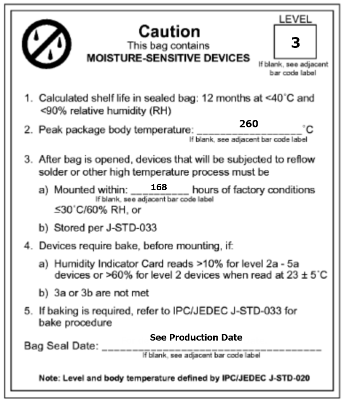
Storage conditions for a delivered module are as follows:
- The moisture-proof bag must be placed in an environment where the temperature is below 30°C and the relative humidity is lower than 70%.
- The shelf life of a dry-packaged product is 6 months from the date when the product is packaged and sealed.
- In the production process, all operators must wear electrostatic rings.
- During operation, strictly prevent the module from getting wet or dirty.
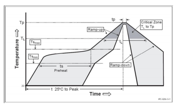
Recommended oven temperature curve
We mount the PCB with the SMT according to the following temperature curve. The peak temperature is 245°C.
Refer to IPC/JEDEC standard. Peak Temperature: <245℃. Number of Times: ≤2.
Storage conditions
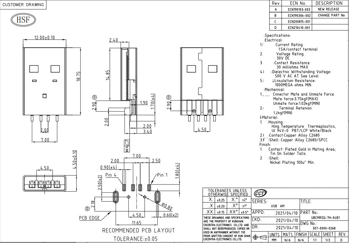
Specifications of terminal
This module adopts the USB2.0 180° sinking-plate straight-leg plug connector. Its specifications are as follows:
| Product model | MOQ (pcs) | Packing method | The number of modules per reel | The number of reels per carton |
|---|---|---|---|---|
| HEWRQU1 | 400 | Honeycomb carton | 200 | 2 |
Appendix: Statement
Federal Communications Commission (FCC) Declaration of Conformity
FCC Caution: Any changes or modifications not expressly approved by the party responsible for compliance could void the user’s authority to operate this equipment.
This device complies with Part 15 of the FCC Rules.
Operation is subject to the following two conditions: (1) This device may not cause harmful interference, and (2) this device must accept any interference received, including interference that may cause undesired operation.
This device and its antenna(s) must not be co-located or operating in conjunction with any other antenna or transmitter. 15.105 Information to the user.
(b) For a Class B digital device or peripheral, the instructions furnished to the user shall include the following or similar statement, placed in a prominent location in the text of the manual:
Note: This equipment has been tested and found to comply with the limits for a Class B digital device, according to part 15 of the FCC Rules.
These limits are designed to provide reasonable protection against harmful interference in a residential installation. This equipment generates, uses, and can radiate radio frequency energy and, if not installed and used by the instructions, may cause harmful interference to radio communications. However, there is no guarantee that interference will not occur in a particular installation. If this equipment does cause harmful interference to radio or television reception, which can be determined by turning the equipment off and on, the user is encouraged to try to correct the interference by one or more of the following measures:
- Reorient or relocate the receiving antenna.
- Increase the separation between the equipment and receiver.
- Connect the equipment to an outlet on a circuit different from that to which
the receiver is connected. - Consult the dealer or an experienced radio/TV technician for help.
This equipment complies with FCC radiation exposure limits set forth for an uncontrolled environment. This equipment should be installed and operated with a minimum distance of 20cm between the radiator and your body.
Radiation Exposure Statement
This equipment complies with FCC radiation exposure limits set forth for an uncontrolled environment.
This transmitter must not be co-located or operating in conjunction with any other antenna or transmitter.
The availability of some specific channels and/or operational frequency bands are country dependent and are firmware programmed at the factory to match the intended destination.
The firmware setting is not accessible by the terminal user.
The terminal product must be labeled in a visible area with the following:
"Contains Transmitter Module 2AFNL-HEWRQU1". This radio module must not be installed to co-locate and operate simultaneously with other radios in the host system, additional testing and equipment authorization may be required to operate simultaneously with other radios.
This LMA does not have RF shielding and is tested and approved as a standalone.
This LMA does not have RF shielding and is tested and approved as a standalone configuration, additional evaluation may be required for any system integrated with this radio module.
Declaration of Conformity European Notice
Hereby, Hangzhou Tuya Information Technology Co., Ltd declares that this WIFI module product is in compliance with essential requirements and other relevant provisions of Directive 2014/53/EC. A copy of the Declaration of conformity can be found at http://www.tuya.com.
- EN 300 328 V2.1.1
- EN 301 489-1 V2.1.1;
- EN 301 489-17 V3.1.1
- EN 62311: 2008
- EN 60950-1:2006+A11:2009+A1:2010+A12:2011+A2:2013
Is this page helpful?
YesFeedbackIs this page helpful?
YesFeedback


