ACW01-B module datasheet
Product overview
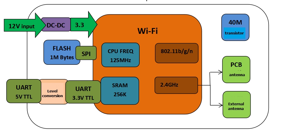
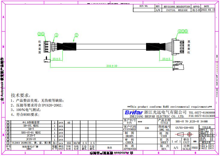
Developed by Tuya, ACW01-B is a Wi-Fi module that is suitable for serial communication in which the level is changed to 3.3V from 5-12V. If added with a 344-mm connection wire and housing, it will become a Wi-Fi adapter board. It consists of a highly integrated RF chip (RTL 8710BN), an extended flash chip, and a DC-DC chip. Besides, it is also built-in with the Wi-Fi network protocol stack and rich library functions. ACW01-B further includes a low-power 32-bit CPU, 1-MB flash memory, and 256-KB SRAM.
The CW01 adapter board is a RTOS platform that integrates all function libraries of the Wi-Fi MAC and TCP/IP. On the basis of the serial communication manner, you can develop embedded Wi-Fi products as required.
The diagram of the architecture of ACW01-B is shown below:
Features
-
Embedded low-power 32-bit CPU, which can also function as an application processor
- Clock rate: 125 MHz
-
Working voltage: 5 to 12V
-
Peripheral: 1 UART (TTL)
-
Wi-Fi connectivity
-
802.11 b/g/n
-
Channels 1 to 14@2.4GHz
-
Support WPA/WPA2 security mode
-
Up to + 20dBm output power in 802.11b mode
-
Support STA/AP/STA+AP working mode
-
Support SmartConfig functions for Android and iOS devices
-
Onboard antenna and external antenna with an IPEX connector
-
Working temperature: -20 to 85℃
-
Applications
- Intelligent building
- Smart household and home appliances
- Medical health care
- Industrial wireless control
- Handheld devices
Module interfaces
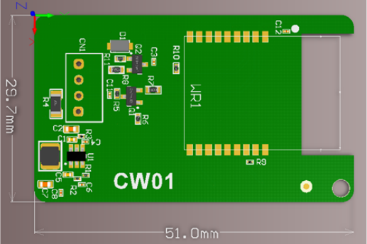
Dimensions and footprint
The dimensions of the adapter board are 29.7 mm (W)×51 mm (L) ×4.5 mm (H), which are shown as belows:
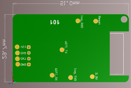
Pin definition
The definitions of pins are shown in the following table:
| Pin number | Symbol | Type | Function |
|---|---|---|---|
| 1 | 12V | P | Power supply pin (5 to 12V) |
| 2 | TXD | I/O | Transmitting interface (5V) |
| 3 | RXD | I/O | Receiving interface (5V) |
| 4 | GND | P | Power supply reference ground |
Note: P indicates a power supply pin and I/O indicates an input/output pin
Definitions on test points
The definitions of test pins are shown in the following table:
| Pin number | Symbol | Type | Function |
|---|---|---|---|
| 1 | 12V | P | Power supply pin (5 to 12V) |
| 2 | TXD | I/O | Transmitting interface (5V) |
| 3 | RXD | I/O | Receiving interface (5V) |
| 4 | GND | P | Power supply reference ground |
| 5 | WIFI_RX | I/O | The firmware authorization interface of the Wi-Fi module |
| 6 | WIFI_TX | I/O | The firmware authorization interface of the Wi-Fi module |
| 7 | LOG_TXD | I/O | The transmitting interface for data burning |
| 8 | LOG_RXD | I/O | The receving interface for data burning |
| 9 | 3.3V | P | Pin for data burning (3.3V) |
| 10 | RST | P | Reset pin |
Note: P indicates a power supply pin and I/O indicates an input/output pin.
Electrical parameters
Absolute electrical parameters
| Parameter | Description | Minimum value | Maximum value | Unit |
|---|---|---|---|---|
| Ts | Storage temperature | -20 | 85 | ℃ |
| VCC | Supply voltage | -0.3 | 13.2 | V |
| ESD voltage (human body model) | TAMB-25℃ | - | 2 | KV |
| ESD voltage (machine model) | TAMB-25℃ | - | 0.5 | KV |
Working conditions
Normal working conditions
| Parameter | Description | Minimum value | Typical value | Maximum value | Unit |
|---|---|---|---|---|---|
| Ta | Working temperature | -20 | - | 85 | ℃ |
| VCC | Working voltage | 4.5 | 5 | 12.5 | V |
| VIL | I/O low level input | -0.3 | - | 5*0.25 | V |
| VIH | I/O high-level input | 5*0.75 | - | 5 | V |
| VOL | I/O low level output | - | - | 5*0.1 | V |
| VOH | I/O high level output | 5*0.8 | - | 5 | V |
| Imax | I/O drive current | - | - | 16 | mA |
Wi-Fi transmission power consumption
TX power consumption:
| Symbol | Mode | Power | Typical value | Unit |
|---|---|---|---|---|
| IRF | 11b | 17dBm | 120 | mA |
| IRF | 11b | 18dBm | 128 | mA |
| IRF | 11g | 15dBm | 113 | mA |
| IRF | 11g | 17.5dBm | 115 | mA |
| IRF | 11n (20M) | 13dBm | 112 | mA |
| IRF | 11n (20M) | 16.5dBm | 118 | mA |
| IRF | 11n (40M) | 13dBm | 106 | mA |
| IRF | 11n (40M) | 16.5dBm | 110 | mA |
Note: The typical value of the current is obtained when the adapter board is at the voltage of 12V.
Wi-Fi receiving power consumption
RX power consumption:
| Symbol | Mode | Typical value | Unit |
|---|---|---|---|
| IRF | CPU Sleep | 90 | mA |
| IRF | CPU Active | 120 | mA |
Power consumption in working mode
| Working mode | Working status, Ta = 25°C | Average value | Maximum value | Unit |
|---|---|---|---|---|
| Connecting to the network fast | The module is connecting to the network | 80 | 120 | mA |
| Connecting to the network fast | The module is connecting to the network | 85 | 115 | mA |
| Connected to the network | The module is connected to the network | 60 | 90 | mA |
RF features
Basic RF features
| Parameter | Description |
|---|---|
| Working frequency | 2.400 to 2.4835 GHz |
| Wi-Fi standard | IEEE 802.11 b/g/n (channels 1 to 14) |
| Data transmission rate | 11b: 1, 2, 5.5, 11 (Mbps) 11g: 6, 9, 12, 18, 24, 36, 48, 54 (Mbps) 11n: HT20 MCS 0 to 7; HT40 MCS 0 to 7 |
| Antenna type | PCB antenna or antenna used with a U.FL RF connector |
Wi-Fi output power
TX power
| Parameter | Minimum value | Typical value | Maximum value | Unit | |
|---|---|---|---|---|---|
| Average RF output power, 802.11b CCK Mode | 1M | - | 18 | - | dBm |
| Average RF output power, 802.11g OFDM Mode | 54M | - | 16 | - | dBm |
| Average RF output power, 802.11n/n20 OFDM Mode | MCS7 | - | 14 | - | dBm |
| Average RF output power, 802.11n/n40 OFDM Mode | MCS7 | - | 14 | - | dBm |
| Frequency error | -20 | - | 20 | ppm |
WiFi Receiving Sensitivity
RX sensitivity
| Parameter | Minimum value | Typical value | Maximum value | Unit | |
|---|---|---|---|---|---|
| PER<8%, RX sensitivity, 802.11b CCK Mode | 1 M | - | -91 | - | dBm |
| PER<10%, RX sensitivity, 802.11g OFDM Mode | 54M | - | -75 | - | dBm |
| PER<10%, RX sensitivity, 802.11n OFDM Mode | MCS7 | - | -72 | - | dBm |
Antenna information
Antenna type
ACW01-B supports two types of antennas: Onboard antenna and external antenna. By default, the onboard PCB antenna is preferred. If you use the external antenna, please contact Tuya sales personnel.
Antenna interference reduction
To ensure optimal Wi-Fi performance when the Wi-Fi module uses a PCB antenna, it is recommended that the antenna be at least 15 mm away from other metal parts.
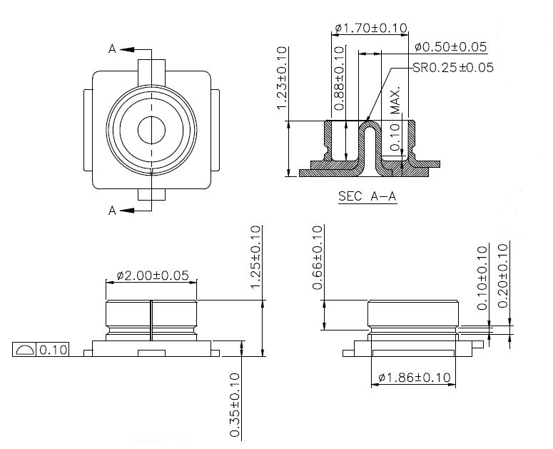
U.FL RF connector
Parameters of the U.FL RF connector are as belows:
Footprint information
Mechanical dimensions
Note: The PCB is 1 mm thick. The dimensional tolerance of the PCB outline is ±0.35 mm, and the dimensional tolerance of the thickness of the PCB is ±0.10 mm.
Footprint of connector
Production instructions
Storage conditions for a delivered module are as follows:
- The moisture-proof bag must be placed in an environment where the temperature is below 30°C and the relative humidity is lower than 85%.
- The shelf life of a dry-packaged product is 6 months from the date when the product is packaged and sealed.
Caution:
- In the production process, all operators must wear electrostatic rings.
- During operation, strictly prevent the module from getting wet or dirty.
Structural parts and housing
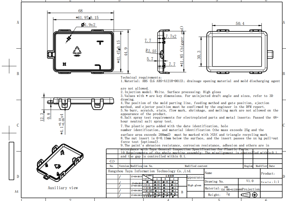
The lower cover of the Wi-Fi adapter board:
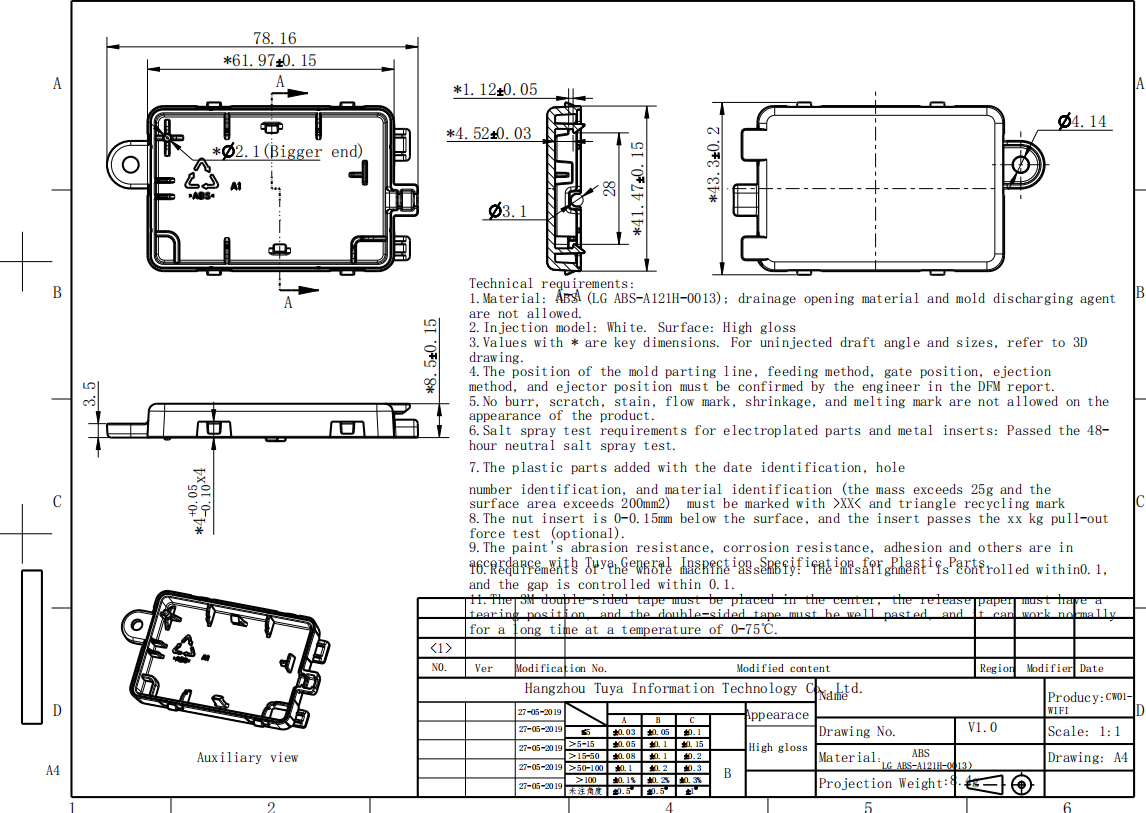
The upper cover of the Wi-Fi adapter board:
Is this page helpful?
YesFeedbackIs this page helpful?
YesFeedback


