TCLWBR Adapter Board Datasheet
Overview
TCLWBR is a Wi-Fi and Bluetooth Low Energy (LE) combo adapter board developed by Tuya Smart. It consists of a highly integrated wireless RF chip RTL8720CF with built-in Wi-Fi stacks and various library functions. TCLWBR combines a low-power KM4 microcontroller unit (MCU), WLAN MAC, and 1T1R (1 transmitter/1 receiver) design. This adapter board provides output frequency up to 100 MHz, 256 KB embedded SRAM, 2 MB flash memory, and configurable GPIOs that can function as digital peripherals for diverse applications.
TCLWBR is a real-time operating system (RTOS), integrated with all Wi-Fi MAC and TCP/IP libraries. All these resources can help develop your own embedded Wi-Fi products.
Features
-
Built-in low-power KM4 MCU that provides output frequency up to 100 MHz and also acts as an application processor.
-
Wi-Fi and Bluetooth connectivity
- IEEE 802.11 b/g/n20.
- Channels 1-14@2.4GHz (CH1-11 for US/CA, and CH1-13 for EU/CN).
- Support security protocols, including WPA2 and WPA2 PSK (AES).
- Support Bluetooth LE 4.2.
- The maximum output power is +20 dBm for IEEE 802.11b transmission.
- Support Wi-Fi Easy Connect (EZ mode) pairing mode on Android and iOS devices.
-
Onboard PCB antenna.
-
It has passed CE and FCC certifications.
-
Operating temperature: -20°C to +85°C.
Applications
- Smart building
- Smart home and electrical appliance
- Smart socket and light
- Industrial wireless control
- Baby monitor
- IP camera
- Smart bus
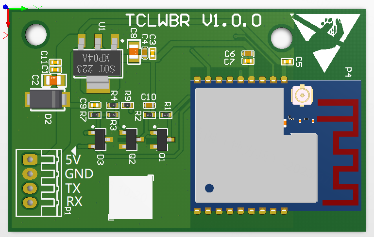
TCLWBR interfaces
Dimensions and footprint
The TCLWBR electrical interface is a PHS connector defined in the following table.
| Pin | Symbol | I/O type | Feature |
|---|---|---|---|
| 1 | 5V | P | 5V power input pin. |
| 2 | GND | P | Ground pin. |
| 3 | TX | I/O | TX pin for serial communication. |
| 4 | RX | I/O | RX pin for serial communication. |
P indicates the power pin, and I/O indicates the input and output pin.
Electrical parameters
Electrical parameters
| Description | Min value | Max value | Unit |
|---|---|---|---|
| Input voltage range | 4.5 | 5.5 | V |
| Operating ambient temperature | -20 | 85 | °C |
| Operating ambient humidity | 0% | 90% | RH |
| Storage ambient temperature | -20 | 85 | °C |
Radio frequency (RF) power
-
Power consumption during TX continuous transmission
Symbol Mode Power Average value Peak (Typical) Unit IRF 802.11b, 11 Mbit/s +17 dBm 217 268 mA IRF 802.11b, 11 Mbit/s 18dBm 231 283 mA IRF 802.11g, 54 Mbit/s +15 dBm 159 188 mA IRF 802.11g, 54 Mbit/s 17.5 dBm 177 213 mA IRF 802.11n, BW20 MCS7 13 dBm 145 167 mA IRF 802.11n, BW20 MCS7 16.5 dBm 165 193 mA -
Power consumption during RX continuous reception
Symbol Mode Average value Peak (Typical) Unit IRF 802.11b, 11 Mbit/s 63 65 mA IRF 802.11g, 54 Mbit/s 65 67 mA IRF 802.11n, HT20 MCS7 65 67 mA
Power consumption in working mode
| Working mode | Status (Ta = 25°C) | Average value | Peak (Typical) | Unit |
|---|---|---|---|---|
| Pairing in EZ mode | The module is in EZ mode. The Wi-Fi network status indicator blinks quickly. | 75 | 324 | mA |
| Connected and idle mode | The module is connected to the cloud. The Wi-Fi network status indicator is steady on. | 64 | 314 | mA |
| Connected and operating mode | The module is connected to the cloud. The Wi-Fi network status indicator is steady on. | 66 | 305 | mA |
| Disconnected mode | The module is disconnected from the cloud. The Wi-Fi network status indicator is steady off. | 66 | 309 | mA |
RF parameters
Basic RF features
| Parameter | Description |
|---|---|
| Frequency range | 2.400 to 2.4835 GHz |
| Wi-Fi standard | IEEE 802.11b/g/n (channels 1 to 14) |
| Bluetooth LE standard | Bluetooth LE 4.2 |
| Data transmission rate | IEEE 802.11b: 1, 2, 5.5, and 11 Mbit/s |
| Data transmission rate | IEEE 802.11g: 6, 9, 12, 18, 24, 36, 48, and 54 Mbit/s |
| Data transmission rate | IEEE 802.11n: HT20 MCS0-7 |
| Antenna type | Onboard PCB antenna with a gain of 2.5 dBi. |
Transmitter (TX) performance
-
TX continuous transmission performance
Parameter Min value Typical value Max value Unit RF average output power, 802.11b CCK mode, 1M - 17.5 - dBm RF average output power, 802.11g OFDM mode, 54M - 14.5 - dBm RF average output power, 802.11n OFDM mode, MCS7 - 13.5 - dBm RF average output power, Bluetooth LE 4.2, 1M - 6.5 - dBm Frequency error -20 - 20 ppm EVM@802.11b CCK 11 Mbit/s mode, 17.5 dBm - - -10 dB EVM@802.11g OFDM 54 Mbit/s mode, 14.5 dBm - - -29 dB EVM@802.11n OFDM MCS7 mode, 13.5 dBm - - -30 dB -
Receiver (RX) performance
Parameter Min value Typical value Max value Unit PER < 8%, RX sensitivity, 802.11b CCK mode, 1M - -91 - dBm PER < 10%, RX sensitivity, 802.11g OFDM mode, 54M - -75 - dBm PER < 10%, RX sensitivity, 802.11g OFDM mode, MCS7 - -72 - dBm PER < 10%, RX sensitivity, Bluetooth LE 4.2, 1M - -93 - dBm
Appendix: Statement
FCC Caution: Any changes or modifications not expressly approved by the party responsible for compliance could void the user’s authority to operate this equipment.
This device complies with Part 15 of the FCC Rules. Operation is subject to the following two conditions: (1) This device may not cause harmful interference, and (2) this device must accept any interference received, including interference that may cause undesired operation.
Note: This equipment has been tested and found to comply with the limits for a Class B digital device, pursuant to part 15 of the FCC Rules. These limits are designed to provide reasonable protection against harmful interference in a residential installation. This equipment generates, uses, and can radiate radio frequency energy and, if not installed and used in accordance with the instructions, may cause harmful interference to radio communications. However, there is no guarantee that interference will not occur in a particular installation. If this equipment does cause harmful interference to radio or television reception, which can be determined by turning the equipment off and on, the user is encouraged to try to correct the interference by one or more of the following measures:
- Reorient or relocate the receiving antenna.
- Increase the separation between the equipment and receiver.
- Connect the equipment to an outlet on a circuit different from that to which
the receiver is connected. - Consult the dealer or an experienced radio/TV technician for help.
Radiation Exposure Statement
This equipment complies with FCC radiation exposure limits set forth for an uncontrolled rolled environment. This equipment should be installed and operated with a minimum distance of 20 cm between the radiator and your body.
Important Note
This radio module must not be installed to co-locate and operate simultaneously with other radios in the host system except in accordance with FCC multi-transmitter product procedures. Additional testing and equipment authorization may be required to operate simultaneously with other radio.
The availability of some specific channels and/or operational frequency bands are country dependent and are firmware programmed at the factory to match the intended destination. The firmware setting is not accessible by the end user.
The host product manufacturer is responsible for compliance with any other FCC rules that apply to the host not covered by the modular transmitter grant of certification. The final host product still requires Part 15 Subpart B compliance testing with the modular transmitter installed.
The end user manual shall include all required regulatory information/warning as shown in this manual, including: This product must be installed and operated with a minimum distance of 20 cm between the radiator and the user body.
This device has got an FCC ID:2ANDL-TCLWBR. The final end product must be labeled in a visible area with the following: "Contains Transmitter Module FCC ID: 2ANDL-TCLWBR"
This device is intended only for OEM integrators under the following conditions:
- The antenna must be installed such that 20cm is maintained between the antenna and users, and
- The transmitter module may not be co-located with any other transmitter or antenna.
As long as the 2 conditions above are met, further transmitter tests will not be required. However, the OEM integrator is still responsible for testing their end-product for any additional compliance requirements required with this module installed.
Declaration of Conformity European notice

Hereby, Hangzhou Tuya Information Technology Co., Ltd declares that this module product is in compliance with essential requirements and other relevant provisions of Directive 2014/53/EU,2011/65/EU. A copy of the Declaration of Conformity can be found at https://www.tuya.com.

This product must not be disposed of as normal household waste, in accordance with the EU directive for waste electrical and electronic equipment (WEEE-2012/19/EU). Instead, it should be disposed of by returning it to the point of sale, or to a municipal recycling collection site.
Is this page helpful?
YesFeedbackIs this page helpful?
YesFeedback


