Develop Product
To develop a product on the Tuya Developer Platform, you need to define product functions, select and customize device panels, develop embedded firmware, and perform a production test.
Step 1: Define product functions
You can set functions for a product, including standard functions, custom functions, and cloud functions.
A product function is the abstraction of a feature that is provided by a smart device. You can use product functions to describe the features and parameters of smart devices. Based on the product functions, the Tuya Developer Platform generates things data models in the cloud to connect to and control the smart devices. This makes product functions and data interactions easy to understand.
DP data type
Tuya Developer Platform allows you to define functions with six data types, including Boolean, value, enum, fault, string, and raw. For more information, see Data type.
Description of DPs
DP IDs 1 to 6: switch
| Data type | Value range |
|---|---|
| Boolean |
|
DP IDs 7 to 12: countdown
Users specify a time delay with a timer. After the timer is done, the device will be automatically turned on or off based on its current ON/OFF state. If the current switch state is ON, it will be turned off when the set time is up. If the current switch state is OFF, it will be turned on when the set time is up. If the switch is turned on or off manually when the timer is running, the timer will be canceled.
| Data type | Value range |
|---|---|
| Value | 0 to 86400, in seconds. |
The values for a Zigbee switch range from 0 to 43200.
DP ID 13: main switch
| Data type | Value range |
|---|---|
| Boolean |
|
The device panel can be used to send DP data for multi-gang switches, so devices can be switched on or off at the same time without the need to control the main switch.
DP ID 14: restart status
Set the switch status after power failure. If a device has multiple switch channels, this DP status applies to all channels.
| Data type | Value range |
|---|---|
| Enum |
|
DP ID 15: indicator status
Set the switch indicator status. If a device has multiple switch channels, this DP status applies to all channels each time the DP data is sent.
| Data type | Value range |
|---|---|
| Enum |
|
DP ID 16: backlight switch
Turn a backlight on or off.
| Data type | Value range |
|---|---|
| Boolean |
|
The backlight works independently from the switch indicator.
DP ID 17: cycle time (string type)
Specify a period to cycle a device between ON and OFF, and set how long you want the ON and OFF state to last in a cycle. After the scheduled task is enabled, the switch turns on by default. Then, the switch turns on or off as scheduled. After the end of the effective period, the switch turns off.
This provides a convenient way to automate light routines such as for cyclic irrigation, pet feeding, and control of lighting scenarios.
| No. | Field | Length (byte) | Property |
|---|---|---|---|
| 1 | Switch + channel ID | 1 |
|
| 2 | Day of week | 1 | Specifies the recurring day(s) of the week. If a bit is set to 1, it means that the task will recur on this specified day weekly. The following table details each field. |
| 3 | Start time | 2 | Valid values: 0 to 1439, in minutes. |
| 4 | End time | 2 | Valid values: 0 to 1439, in minutes. |
| 5 | Duration of ON state | 2 | Valid values: 1 to 1440, in minutes. |
| 6 | Duration of OFF state | 2 | Valid values: 1 to 1440, in minutes. |
Description of recurring day(s) setting
If all the bits are 0, it indicates a one-time task. If a bit is set to 1, it indicates the task is run on that day of a week. For example, 0x42 means that the task is run on Saturday and Monday. The task switch must be enabled.
| Reserved | Saturday | Friday | Thursday | Wednesday | Tuesday | Monday | Sunday |
|---|---|---|---|---|---|---|---|
| bit7 | bit6 | bit5 | bit4 | bit3 | bit2 | bit1 | bit0 |
DP ID 18: random (string type)
Set the period when the task is run and the recurring day(s) of the week. The lights will go on and off once based on a random rule. At the start time of the vacation timing, the switch turns on by default. At the end of the vacation timing, the switch turns off.
When users go out for a long time, random timing can be used to turn the lights on or off just as if someone was at home, in order to deter burglars.
| No. | Field | Length (byte) | Property |
|---|---|---|---|
| 1 | Switch + channel ID | 1 |
|
| 2 | Day of week | 1 | Specifies the recurring day(s) of the week. If a bit is set to 1, it means that the task will recur on this specified day weekly. The following table details each field. |
| 3 | Start time | 2 | Valid values: 0 to 1439, in minutes. |
| 4 | End time | 2 | Valid values: 0 to 1439, in minutes. |
Description of recurring day(s) setting
If all the bits are 0, it indicates a one-time task. If a bit is set to 1, it indicates the task is run on that day of a week. For example, 0x42 means that the task is run on Saturday and Monday. The task switch must be enabled.
| Reserved | Saturday | Friday | Thursday | Wednesday | Tuesday | Monday | Sunday |
|---|---|---|---|---|---|---|---|
| bit7 | bit6 | bit5 | bit4 | bit3 | bit2 | bit1 | bit0 |
DP ID 19: switch inching (string type)
Set a period for power-off delay timing. Then, after power on, the switch stays in the ON state for the specified period and automatically turns off. This smart scene avoids the frequent setting of countdowns.
Inching switches are widely used in public places such as corridors and corridors. For example, if an inching in-wall switch is delayed for one minute to turn off and it is connected to a corridor light, users only need to turn on the light whenever they pass through the corridor. The switch automatically turns the light off one minute later. Users do not need to set a countdown timer or manually turn the light off.
| No. | Field | Length (byte) | Property |
|---|---|---|---|
| 1 | Switch + channel ID | 1 |
|
| 2 | Inching period | 2 | Valid values: 1 to 65535, in seconds. |
DP IDs 20 to 28: energy metering
| DP | Data type | Value range |
|---|---|---|
| Increased power usage | Value | 0 to 50000, in kWh. |
| Actual current | Value | 0 to 30000, in mA. |
| Actual voltage | Value | 0 to 5000, in V. |
| Actual power | Value | 0 to 50000, in W. |
| Production test result bit | Value | 0 to 5 |
| Voltage calibration parameter | Value | 0 to 1000000 |
| Current calibration parameter | Value | 0 to 1000000 |
| Power calibration parameter | Value | 0 to 1000000 |
| Battery calibration parameter | Value | 0 to 1000000 |
The energy metering DP can be used only after electricity statistics is enabled.
DP IDs 29 to 34: restart status (individual control)
Set the switch status after power failure. If a device has multiple switch channels, this DP status applies to all channels.
| Data type | Value range |
|---|---|
| Enum | off: The switch will be OFF after the power supply is reconnected.on: The switch will be ON after the power supply is reconnected.memory: The switch resumes its previous status after the power supply is reconnected. |
If the switch status after power on can be controlled by both the main switch DP and the individual control DP, the main switch DP prevails. In this case, the setting of the main switch DP status takes effect immediately for all individual switches. The DP status setting of an individual switch does not modify the DP status of the main switch and other individual switches.
DP ID 209: cycle schedule (raw type)
Specify a period to cycle a device between ON and OFF, and set how long you want the ON and OFF state to last in a cycle. After the scheduled task is enabled, the switch turns on by default. Then, the switch turns on or off as scheduled. After the end of the effective period, the switch turns off.
This provides a convenient way to automate light routines such as for cyclic irrigation, pet feeding, and control of lighting scenarios.
| No. | Field | Length (byte) | Property |
|---|---|---|---|
| 1 | Version number | 1 | |
| 2 | Length | 1 | |
| 3 | Switch + channel ID | 1 |
|
| 4 | Day of week | 1 | Specifies the recurring day(s) of the week. If a bit is set to 1, it means that the task will recur on this specified day weekly. The following table details each field. |
| 5 | Start time | 2 | Valid values: 0 to 1439, in minutes. |
| 6 | End time | 2 | Valid values: 0 to 1439, in minutes. |
| 7 | Duration of ON state | 2 | Valid values: 1 to 1440, in minutes. |
| 8 | Duration of OFF state | 2 | Valid values: 1 to 1440, in minutes. |
Description of recurring day(s) setting
If all the bits are 0, it indicates a one-time task. If a bit is set to 1, it indicates the task is run on that day of a week. For example, 0x42 means that the task is run on Saturday and Monday. The task switch must be enabled.
| Reserved | Saturday | Friday | Thursday | Wednesday | Tuesday | Monday | Sunday |
|---|---|---|---|---|---|---|---|
| bit7 | bit6 | bit5 | bit4 | bit3 | bit2 | bit1 | bit0 |
DP ID 210: random schedule (raw type)
Set the period when the task is run and the recurring day(s) of the week. The lights will go on and off once based on a random rule. At the start time of the vacation timing, the switch turns on by default. At the end of the vacation timing, the switch turns off.
When users go out for a long time, random timing can be used to turn the lights on or off just as if someone was at home, in order to deter burglars.
| No. | Field | Length (byte) | Property |
|---|---|---|---|
| 1 | Version number | 1 | / |
| 2 | Length | 1 | / |
| 3 | Switch + channel ID | 1 |
|
| 4 | Day of week | 1 | Specifies the recurring day(s) of the week. If a bit is set to 1, it means that the task will recur on this specified day weekly. The following table details each field. |
| 5 | Start time | 2 | Valid values: 0 to 1439, in minutes. |
| 6 | End time | 2 | Valid values: 0 to 1439, in minutes. |
Description of recurring day(s) setting
If all the bits are 0, it indicates a one-time task. If a bit is set to 1, it indicates the task is run on that day of a week. For example, 0x42 means that the task is run on Saturday and Monday. The task switch must be enabled.
| Reserved | Saturday | Friday | Thursday | Wednesday | Tuesday | Monday | Sunday |
|---|---|---|---|---|---|---|---|
| bit7 | bit6 | bit5 | bit4 | bit3 | bit2 | bit1 | bit0 |
Custom function
You can add custom functions that are not supported by standard functions. For more information, see Custom Function.
Cloud function
Cloud functions support cloud timing and jumping page. For more information, see Advanced Function.
- Cloud timing: allows you to implement the schedule feature without embedded development.
- Jumping page: enables navigating to another web page, such as an online store or user guide.
Step 2: Configure a panel
After the function definition step, you can configure a favorite app control panel for the product. A panel is a GUI-based program that runs on top of a mobile app to control smart products. For more information about panel configurations and development tutorials, see Design App UI and Panel Development.
Step 3: Design hardware
Hardware development involves hardware design and embedded development. For certain electrical products, the no-code development solution is available. Therefore, you only need to set parameters in a configuration file before firmware can be generated without coding. In addition, you can implement custom development based on the MCU SDK or TuyaOS as needed.
Hardware design reference
Generic design
| No. | Design type |
|---|---|
| 1 | Power Design |
| 2 | Compliance Design for Electrical Product |
System on chip (SoC) solution
| No. | Protocol type | Number of switch channels | Power supply type | Recommended module |
|---|---|---|---|---|
| 1 | Wi-Fi & Bluetooth Low Energy (LE) | 1- to 4-gang switch | With neutral | CB3S, CBU, CBU-IPEX |
| 2 | Zigbee | 1- to 4-gang switch | With neutral | ZS3L, ZSU, ZSU-IPEX |
| 3 | Zigbee | 1- to 4-gang switch | Without neutral | ZS3L, ZSU, ZSU-IPEX |
| 4 | Bluetooth mesh | 1- to 4-gang switch | With neutral | BT3L, BTU, BTU-IPEX |
| 5 | Bluetooth mesh | 1- to 4-gang switch | Without neutral | BT3L, BTU, BTU-IPEX |
To get the materials of open source hardware, contact Tuya’s account manager.
Step 4: Perform embedded programming
Embedded programming is classified into no-code development (also known as SoC solution), MCU low-code development, and TuyaOS development. In this step, you must implement device integration and business programming.
No-code development
In this solution, you can set parameters in a configuration file to generate firmware without coding. For more information, see the instructions on the Tuya Developer Platform.
MCU SDK
MCU low-code development enables products with built-in microcontrollers to connect to the cloud and become connected. Tuya provides one-stop IoT development services including the three essentials for typical IoT products, namely network modules, mobile apps, and cloud services. With Tuya’s MCU SDK, all-in-one mobile apps, and control panels, you can focus on application development simply, connect your product to the Tuya Developer Platform easily, and benefit from the cloud services quickly.
For more information, see MCU Low-Code Development.
Smart switches can be developed based on multiple protocols, including Zigbee, Wi-Fi and Bluetooth combo, and Bluetooth mesh. For more information, see:
- Wi-Fi Common Solution
- Bluetooth Common Solution
- Bluetooth Mesh Common Solution
- Zigbee Common Solution
TuyaOS
Built on top of the RTOS, Linux, and Non-OS, TuyaOS is a distributed and platform-agnostic IoT operating system.
With a standard kernel at the core, TuyaOS is designed to tackle the heterogeneity of platforms, systems, and protocols in order to enable quick and reliable integration, interconnection, and interoperability.
The tiered and plug-and-play architecture design allows you to quickly tailor a solution based on your hardware resources hence reducing the cost of development with high cost performance. The efficient remote procedure call (RPC) mechanism and proprietary data point (DP) protocols make communication across protocols possible and easy.
Specifically, the following types of devices can be connected based on this solution:
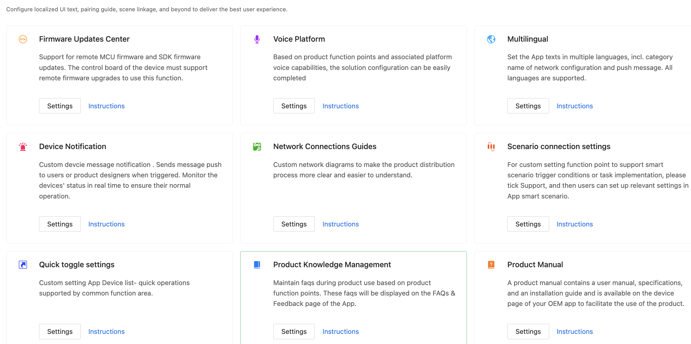
Step 5: Configure product
In this step, the following settings are involved: firmware updates, voice capabilities, multilingual settings, device notifications, device pairing, smart scenes, quick toggle settings, product knowledge, and product manuals. Based on these settings, global cloud services are employed to promote the personalized user experience. You can update these settings and make them effective immediately without the need to deliver the devices again.
Particularly, multilingual settings, device pairing, voice capabilities, and smart scenes require precision and localized management based on the target user locations and the specific pairing methods and device features.
For more information, see:
Step 6: Flash firmware and authorize chip
Flash the device with the firmware and Tuya’s license to connect the device to the cloud. Tuya provides multiple firmware flashing and authorization methods for you to connect the following types of devices:
Step 7: Test product
Before your product can be released on the Tuya Developer Platform, you must submit a product test report. To test the product, you can download and run use cases, use Tuya’s Cloud Test app, or subscribe to Tuya Test Service.
Download and run use cases
For certain product categories, you can download use cases from the Tuya Test Service page, run the use cases, and then submit test reports.
Cloud Test
Tuya’s Cloud Test app is provided with multiple test modes for you to accelerate troubleshooting based on functional modules. This enables all-in-one tests for the device status and interaction link.
For more information, see Cloud Test App.
Tuya Test Service
For more information, see Tuya Test Service.
Step 8: Release product
In this step, you can release your project.
Next steps
Pass product certifications
A product must pass certain certifications before it is permitted to be sold. By virtue of rich experience in smart product development, Tuya provides a set of product certification solutions. You can choose among these solutions to meet your product category and certification requirements. For more information, see Product Certificate.
Is this page helpful?
YesFeedbackIs this page helpful?
YesFeedback


