Develop Product
This topic walks you through how to develop a socket or power strip product on the Tuya Developer Platform. You will learn about function definition, panel configuration, hardware development, embedded system development, product configuration, firmware flashing and authorization, product testing, and product release.
Step 1: Function definition
The product function is broken down into three types, standard functions, custom functions, and advanced functions. The platform allows you to define functions with six data types, including Boolean, value, enum, fault, string, and raw. For more information, see Product Functions.
DP description
-
DP IDs 1 to 8: Switch
Data type Value range Boolean 0: Off1: On
-
DP IDs 9 to 16: Countdown
Users specify a time delay. After the timer is done, the device automatically turns on or off based on its current on/off state. If the switch is on, it can be set to automatically turn off. If the switch is off, it can be set to automatically turn on. If the switch is interrupted by manual on/off control when the timer is running, the timer will be canceled.
Data type Value range Value 0 to 86400, in seconds. The valid values range from 0 to 43200 for the Zigbee protocol.
-
DP IDs 17 to 26: Energy metering
DP Data type Value range Energy usage Value 0 to 50000, in kWh. Actual current Value 0 to 30000, in mA. Actual voltage Value 0 to 5000, in V. Actual power Value 0 to 50000, in W. Production test result Value 0 to 5 Voltage calibration factor Value 0 to 1000000 Current calibration factor Value 0 to 1000000 Power calibration factor Value 0 to 1000000 Electricity calibration factor Value 0 to 1000000 Fault alert Fault ov_cr: Over-current.ov_vol: Over-voltage.ov_pwr: Over-power.ls_cr: Under-current.ls_vol: Under-voltage.ls_pow: Under-power.
Energy metering is available after you subscribe to the metering feature.
Energy status reporting
-
Current: None
-
Voltage: The rate of change is less than 2%.
-
Power: The rate of change is less than 20%.
The energy data is collected every 30 seconds. If the collected data meets the above criteria, the module reports energy status every one hour. If the rate of change of either the voltage or power does not meet the above criteria in two data collection events, the module will report the current, voltage, and power to the cloud.
In this case, the frequency of data collection will be changed to five seconds. Otherwise, the frequency stays unchanged.
To reduce the workload in the cloud, make sure to follow the above principle for energy status reporting. When the control panel on the app is opened, it will send a status request to the device. In this case, the device syncs data with the app every five seconds to ensure users view the actual energy data.
Incremental and full data reporting
-
Incremental data reporting
Either of the following can trigger incremental data reporting: The energy usage is greater than or equal to 0.1 kWh within a time period of 10 to 30 minutes. The energy usage is greater than or equal to 0.001 kWh within a time period of no less than 30 minutes.
-
Full data reporting
Each time energy usage is increased by 0.01 kWh, full data reporting is triggered.
To adopt incremental and full data reporting:
- For devices connected to the cloud through a gateway such as Zigbee or Bluetooth devices, full data reporting is adopted.
- For devices directly connected to the cloud such as Wi-Fi devices, incremental data reporting is adopted.
Device offline
-
If the device is not connected to the internet after power on, it cannot sync the clock with the server time. Therefore, it caches the energy data and reports it to the cloud when the internet is connected. The cached data is taken as the energy usage of the day when the device is connected to the cloud.
-
If the device is disconnected from the internet, it can retain the energy data by day and report the cached energy data that contains the timestamp. With the 24-hour time format, the device can retain 10 records of energy data, namely energy data for 10 days. The data generated after the 10th day will be retained in the 10th record and reported to the cloud on the next internet connection.
-
DP ID 38: Relay status
Set how the device will react when power is restored after an outage. The setting applies to all channels of the device.
Data type Value range Enum off: The device will be off when power is restored.on: The device will be on when power is restored.memory: The device resumes its previous state when power is restored.
-
DP ID 39: Indicator mode
Set how the indicator works. The setting applies to all channels of the device.
Data type Value range Enum none: The indicator is steady off.relay: The indicator behaves as the on/off state of the device.pos: The indicator behaves as opposed to the on/off state of the device, which can signal the position of the device in dark.on: The indicator is steady on.
-
DP ID 40: Child lock
When the child lock is enabled, the physical button will become disabled.
Data type Value range Boolean - 0: Child lock is disabled.
- 1: Child lock is enabled. The physical button becomes disabled.
-
DP ID 41: Cycle timing (string)
A cycle timer allows users to cycle a device between on and off during a set time period and specify the recurring day(s) of a week. By default, the device is on when the task starts and is off when the task ends.
A cycle timer will cycle a device between the on and off states during a set time period. This provides a convenient way to automate light routines such as for plant grow lights or lights for homes or businesses.
No. Field Length Property 1 Switch + channel ID 1 - Bit 0: indicates the on/off state of the node.
- Bit 1 to bit 7: indicates the channel to which the node is applied.
0x03is0000 0011in binary. Bit 0 indicates whether the node is turned on. Bit 1 to bit 7 indicates whether a channel is applied.1represents the ON state.2 Day of week 1 Specifies the recurring day(s). If a bit is set to 1, it means that the task will recur on this specified day weekly. The following table details each field.3 The start time 2 Value range: 0 to 1439, in minutes. 4 The end time 2 Value range: 0 to 1439, in minutes. 5 The ON state duration 2 Value range: 1 to 1440, in minutes. 6 The OFF state duration 2 Value range: 1 to 1440, in minutes. Description of recurring day(s)
If all the bits are
0, it indicates a one-time task. If a bit is set to1, it indicates the task recurs on that day every week. For example,0x42is0100 0010in binary, indicating the task is scheduled to run every Saturday and Monday. The schedule is available only when the corresponding task is turned on.Reserved Saturday Friday Thursday Wednesday Tuesday Monday Sunday Bit 7 Bit 6 Bit 5 Bit 4 Bit 3 Bit 2 Bit 1 Bit 0 -
DP ID 42: Random timing (string)
Users can schedule a task to turn on and off their devices randomly during the set time period. By default, the device is on when the task starts and is off when the task ends.
Random timing helps to keep the home secure because it can create the illusion that someone is at home while users are away.
No. Field Length Property 1 Switch + channel ID 1 - Bit 0: indicates the on/off state of the node.
- Bit 1 to bit 7: indicates the channel to which the node is applied.
0x03is0000 0011in binary. Bit 0 indicates whether the node is turned on. Bit 1 to bit 7 indicates whether a channel is applied.1represents the ON state.2 Day of week 1 Specifies the recurring day(s). If a bit is set to 1, it means that the task will recur on this specified day weekly. The following table details each field.3 The start time 2 Value range: 0 to 1439, in minutes. 4 The end time 2 Value range: 0 to 1439, in minutes. Description of recurring day(s)
If all the bits are
0, it indicates a one-time task. If a bit is set to1, it indicates the task recurs on that day every week. For example,0x42is0100 0010in binary, indicating the task is scheduled to run every Saturday and Monday. The schedule is available only when the corresponding task is turned on.Reserved Saturday Friday Thursday Wednesday Tuesday Monday Sunday Bit 7 Bit 6 Bit 5 Bit 4 Bit 3 Bit 2 Bit 1 Bit 0 -
DP ID 43: Inching switch (string)
The inching switch can enable a device to be turned off automatically after it is turned on for a specified period, regardless of how it is activated.
For example, with the inching feature enabled, after a socket that controls a light bulb is turned on, it can come off automatically after the specified time period has elapsed such as one minute.
No. Field Length Property 1 Switch + channel ID 1 - Bit 0: indicates the on/off state.
- Bit 1 to bit 7: indicates the channel ID.
2 Inching duration 2 Value range: 1 to 65535, in seconds. -
DP ID 51: Overcharge protection
When the child lock is enabled, the physical button will become disabled.
Data type Value range Boolean - 0: Overcharge protection is disabled.
- 1: Overcharge protection is enabled. When power is less than 3W for 40 minutes, the power supply will be turned off.
-
DP ID 209: Cycle timing (raw)
A cycle timer allows users to cycle a device between on and off during a set time period and specify the recurring day(s) of a week. By default, the device is on when the task starts and is off when the task ends.
A cycle timer will cycle a device between the on and off states during a set time period. This provides a convenient way to automate light routines such as for plant grow lights or lights for homes or businesses.
No. Field Length Property 1 Version number 1 2 Length 1 3 Switch + channel ID 1 - Bit 0: indicates the on/off state of the node.
- Bit 1 to bit 7: indicates the channel to which the node is applied.
0x03is0000 0011in binary. Bit 0 indicates whether the node is turned on. Bit 1 to bit 7 indicates whether a channel is applied.1represents the ON state.4 Day of week 1 Specifies the recurring day(s). If a bit is set to 1, it means that the task will recur on this specified day weekly. The following table details each field.5 The start time 2 Value range: 0 to 1439, in minutes. 6 The end time 2 Value range: 0 to 1439, in minutes. 7 The ON state duration 2 Value range: 1 to 1440, in minutes. 8 The OFF state duration 2 Value range: 1 to 1440, in minutes. Description of recurring day(s)
If all the bits are
0, it indicates a one-time task. If a bit is set to1, it indicates the task recurs on that day every week. For example,0x42is0100 0010in binary, indicating the task is scheduled to run every Saturday and Monday. The schedule is available only when the corresponding task is turned on.Reserved Saturday Friday Thursday Wednesday Tuesday Monday Sunday Bit 7 Bit 6 Bit 5 Bit 4 Bit 3 Bit 2 Bit 1 Bit 0 -
DP ID 210: Random timing (raw)
Users can schedule a task to turn on and off their devices randomly during the set time period. By default, the device is on when the task starts and is off when the task ends.
Random timing helps to keep the home secure because it can create the illusion that someone is at home while users are away.
No. Field Length Property 1 Version number 1 / 2 Length 1 / 3 Switch + channel ID 1 - Bit 0: indicates the on/off state of the node.
- Bit 1 to bit 7: indicates the channel to which the node is applied.
0x03is0000 0011in binary. Bit 0 indicates whether the node is turned on. Bit 1 to bit 7 indicates whether a channel is applied.1represents the ON state.4 Day of week 1 Specifies the recurring day(s). If a bit is set to 1, it means that the task will recur on this specified day weekly. The following table details each field.5 The start time 2 Value range: 0 to 1439, in minutes. 6 The end time 2 Value range: 0 to 1439, in minutes. Description of recurring day(s)
If all the bits are
0, it indicates a one-time task. If a bit is set to1, it indicates the task recurs on that day every week. For example,0x42is0100 0010in binary, indicating the task is scheduled to run every Saturday and Monday. The schedule is available only when the corresponding task is turned on.Reserved Saturday Friday Thursday Wednesday Tuesday Monday Sunday Bit 7 Bit 6 Bit 5 Bit 4 Bit 3 Bit 2 Bit 1 Bit 0
Custom functions
You can add custom functions that are not supported by standard functions. For more information, see Custom Functions.
Advanced features
Advanced functions support cloud timing and jumping page. For more information, see Advanced Functions.
- Cloud timing: allows you to implement the schedule feature without embedded development.
- Jumping page: enables navigating to another web page, such as an online store and user guide.
Step 2: Panel configuration
Configure an app panel that allows users to interact with the device. For more information, see Design App UI and Panel Development.
Step 3: Hardware development
Hardware development is broken down into two parts, hardware design and embedded development. Some electrical products are available for no-code development, allowing you to develop firmware simply by editing the parameters without coding. You can also choose the MCU SDK or TuyaOS-based SDK for custom development.
Hardware design reference
-
Generic hardware design
No. Types 1 Power supply 2 Product compliance -
SoC solution
No. Wireless protocol Product type 1 Wi-Fi and Bluetooth Low Energy (LE) combo 1- to 8-gang socket or power strip 2 Wi-Fi and Bluetooth Low Energy (LE) combo 1- to 8-gang socket or power strip with energy monitoring 3 Zigbee 1- to 5-gang socket or power strip 4 Zigbee 1- to 3-gang socket or power strip with energy monitoring 5 Bluetooth mesh 1- to 5-gang socket or power strip Contact the account manager or submit a service ticket to request the open source hardware materials.
Step 4: Embedded development
Embedded development is broken down into SoC-based no-code development, MCU SDK development, and TuyaOS-based SDK development.
No-code solution
With no-code development, you can edit the configuration parameters to generate the firmware.
MCU SDK
The MCU SDK solution enables products with built-in microcontrollers to connect to the cloud and become connected. Tuya provides one-stop IoT development services including the three essentials for typical IoT products, namely network modules, mobile apps, and cloud services. With Tuya’s MCU SDK, all-in-one mobile apps, and control panels, you can focus on application development simply, connect your product to the Tuya Developer Platform easily, and benefit from the cloud services quickly.
For more information, see MCU SDK Development.
You can develop sockets or power strips that communicate over protocols including Wi-Fi and Bluetooth combo, Bluetooth mesh, and Zigbee. For more information, see the following documentation:
- Wi-Fi Generic Solution
- Bluetooth Generic Solution
- Bluetooth Mesh Generic Solution
- Zigbee Generic Solution
TuyaOS
Built on top of the RTOS, Linux, and Non-OS, TuyaOS is a distributed and platform-agnostic IoT operating system.
With a standard kernel at the core, TuyaOS is designed to tackle the heterogeneity of platforms, systems, and protocols in order to enable quick and reliable integration, interconnection, and interoperability.
The tiered and plug-and-play architecture design allows you to quickly tailor a solution based on your hardware resources hence reducing the cost of development with high cost performance. The efficient remote procedure call (RPC) mechanism and proprietary data point (DP) protocols make communication across protocols possible and easy.
For more information about the development guide, see the following documentation:
- Networked Product Development Framework
- Bluetooth Sub-Device Development Framework
- Zigbee Sub-Device Development Framework
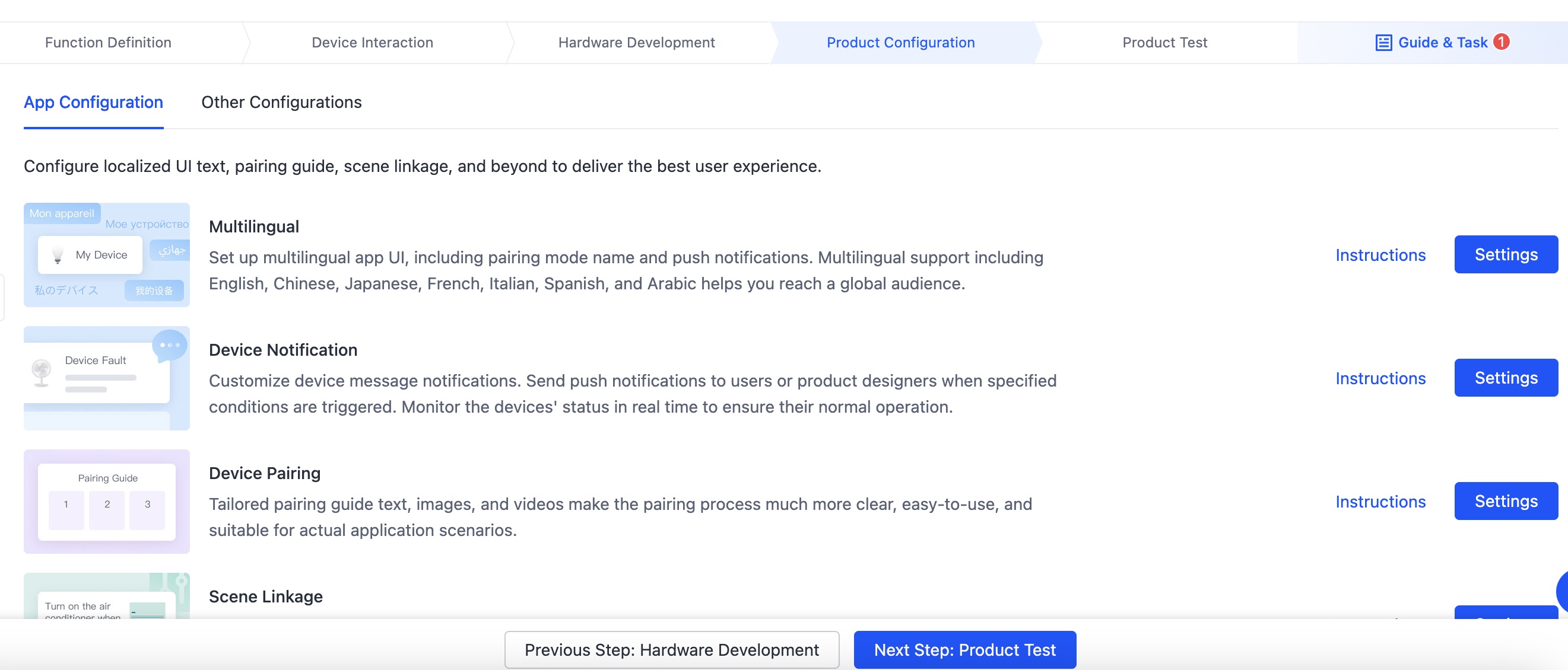
Step 5: Product configuration
Product configuration helps you set and manage different features in one place, including firmware updates, voice assistant integration, multi-language support, pairing guides, scenes and automation, quick toggle, knowledge base, and user guide. These features can help you distribute products worldwide and improve user experiences with continuous iteration. The feature can take effect immediately after you finish the configuration without hardware replacement.
Take care of the multi-language support, pairing guides, voice assistant integration, and scenes and automation, which require product- and market-specific configuration and management.
For more information, see the following documentation:
Step 6: Flashing and authorization
The firmware and license must be flashed to the module to enable the connection to the cloud services. Tuya provides different solutions to achieve this purpose. You can select one that best fits your needs.
Step 7: Product testing
Before you release a product on the Tuya Developer Platform, you need to submit a test report. Alternatively, you can use the Cloud Test app and the test cases to perform product tests.
Test cases download
For certain categories, you can download the test cases and submit a report on the Testing Service page.
Cloud Test app
To help you quickly identify issues for troubleshooting, the Cloud Test app enables integrated testing on hardware functionalities and data interaction in terms of various test modes.
For more information, see Cloud Test App.
Testing services
For more information, see Tuya Test Service.
Step 8: Product release
After you submit the test result, you can release your product on the Tuya Developer Platform.
Next steps
To roll out your product in target markets, you need to get your product certified for each market’s regulations. With proven technologies and certification services, Tuya provides a variety of portfolios to meet your product certification needs. For more information, see Product Certificate.
Is this page helpful?
YesFeedbackIs this page helpful?
YesFeedback


